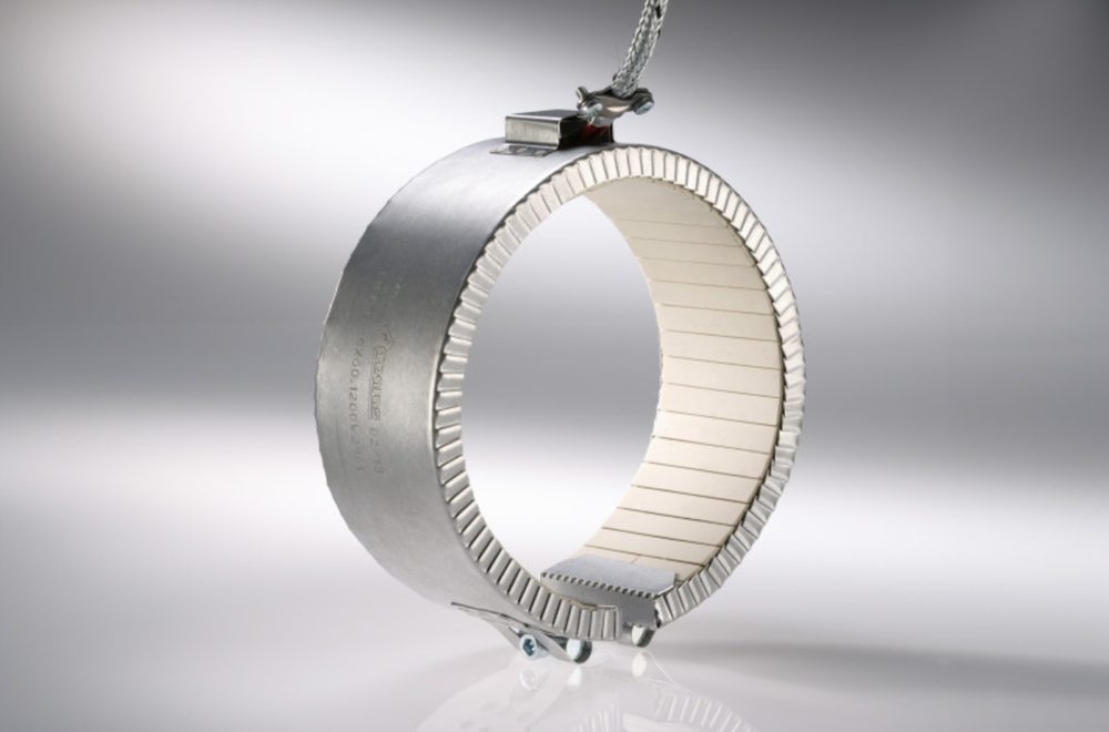
Heating Bands
Heating tapes provide uniform external heating for cylinders, nozzles, and other round components. They are primarily used in injection molding and extrusion processes. The operating temperature is the primary factor in determining which type is appropriate.
We manufacture any technically feasible heating tape based on drawings or samples.
Are you looking for a heating solution for flat surfaces rather than round components? You can find ceramic heating mats and Mikanite surface heaters at Surface heating elements.
Click here to configure your heating tape
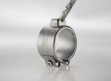
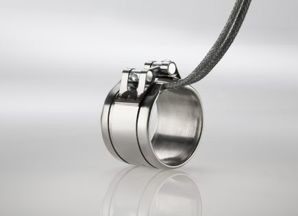
Nozzle heating bands heat the nozzles and gate systems of injection molding machines. They are flat in design, have a thin wall thickness, and transfer heat directly to the mold. Typical applications include hot runner systems, gate sockets, and small cylinder diameters where there is not enough space for a standard heating band.
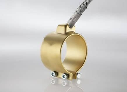
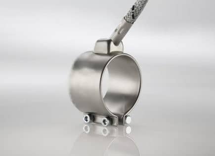
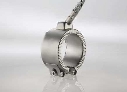
Depending on the temperature range, three models are available: brass up to 280 °C, stainless steel up to 350 °C, and stainless steel with ceramic insulation up to 600 °C. All models are available with an integrated thermocouple upon request, in either Type J, Type K, or PT100.
Brass version up to 280 °C
Stainless steel version up to 350 °C
Ceramic insulation up to 600 °C
| Characteristic | Brass | Stainless steel | Ceramically insulated |
| Diameter | 25 to 110 mm | 30 to 340 mm | 25 to 340 mm |
| Wide | 20 to 60 mm | 20 to 220 mm | 20 to 220 mm |
| Voltage | 230 V | 230 V | 230 V |
| Operating temperature | up to 280 °C | up to 350 °C | up to 600 °C |
| Jacket material | Brass | Stainless steel | Stainless steel, ceramic-insulated |
| Wall thickness | 3.5 mm | 4.5 to 5.0 mm | 8.5 mm |
| Heating conductor Wire | Nickel-Chromium 80/20 | Nickel-Chromium 80/20 | Nickel-Chromium 80/20 |
| Thermocouple | Optional types: J, K, PT100 | Optional types: J, K, PT100 | Optional types: J, K, PT100 |
In special cases, these values may be exceeded. Please contact us, and we will review your application.
Mica heating bands, also known as micanite heating bands, are the standard solution for temperatures up to 350 °C. The heating element is sandwiched between two layers of micanite, and the outer jacket is made of AISI 430 stainless steel. Thanks to their flexible design, they can be installed even in tight spaces. Round versions are called ring heating bands, and foldable variants are available.
Typical applications include plastics processing, hot-runner systems, and packaging equipment. Four models are available.
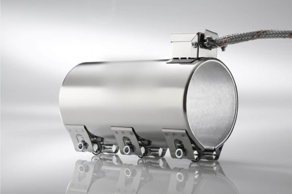
HKE 50 Standard Model
The classic mica heating band. It is wrapped around the cylinder and secured with a tension clamp or clamps. The right choice for most applications in plastics processing.
Design
Layer Structure
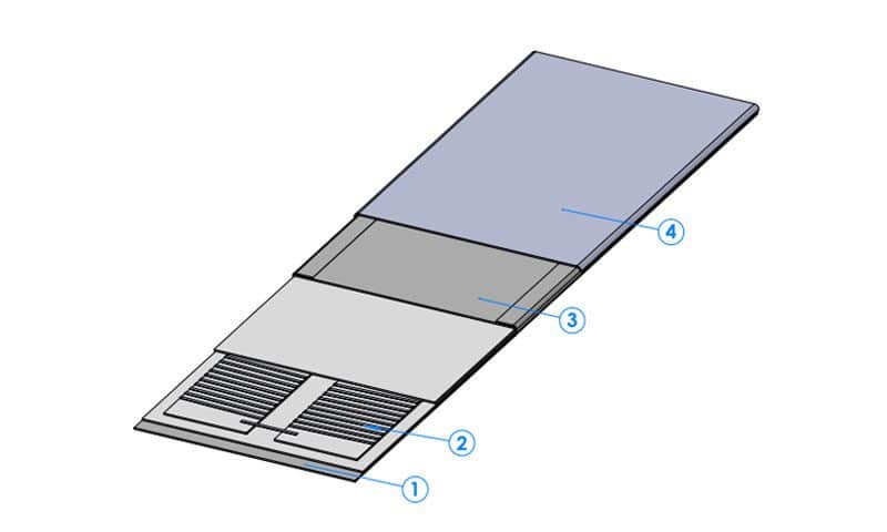
Construction: 1. Bottom panel, 2. Insulated sandwich panel with resistance winding, 3. Cover panel, 4. Outer panel
HKE 52 with heat distribution plate
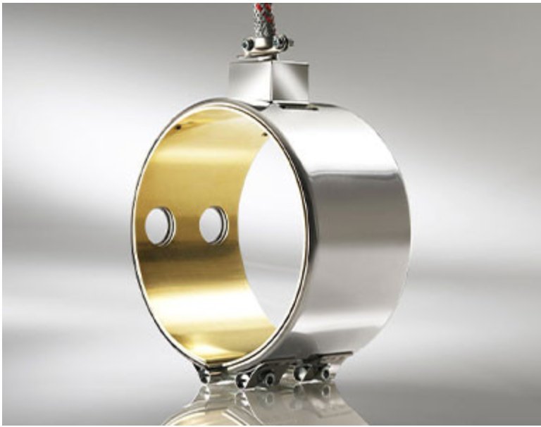
A 1.5 mm-thick copper sheet inserted into the heating tape distributes heat more evenly across the surface. This is useful wherever the heating tape has multiple holes or cutouts and temperature variations would otherwise occur. The copper sheet can be identified by its gold-colored inner side.
Design
Layer Structure
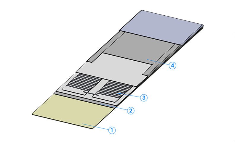
Construction: 1 Copper heat distribution plate, 2 Insulation sandwich with resistance winding, 3 Cover plate, 4 Outer plate
HKE 53, internal clamping version
This heating tape is not wrapped around the outside of the cylinder but is secured inside the pipe. The configuration is reversed, with the heating surface facing outward. This allows pipes and hollow structures to be heated from the inside. This design is rarely available on the market.
Standard Closure
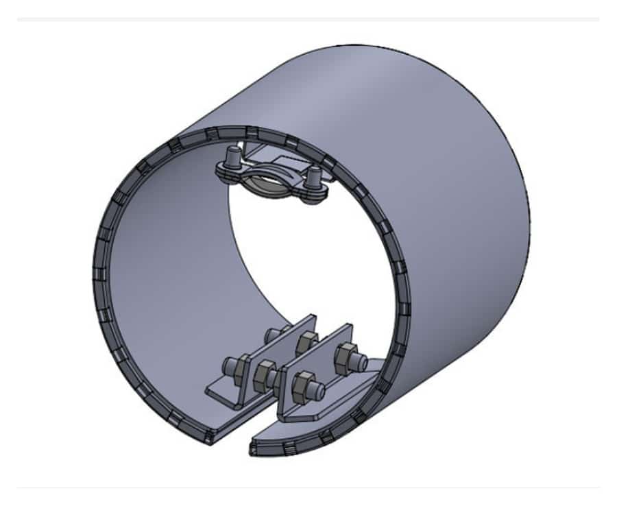
Wedge Closure
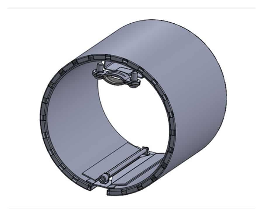
Eccentric Closure
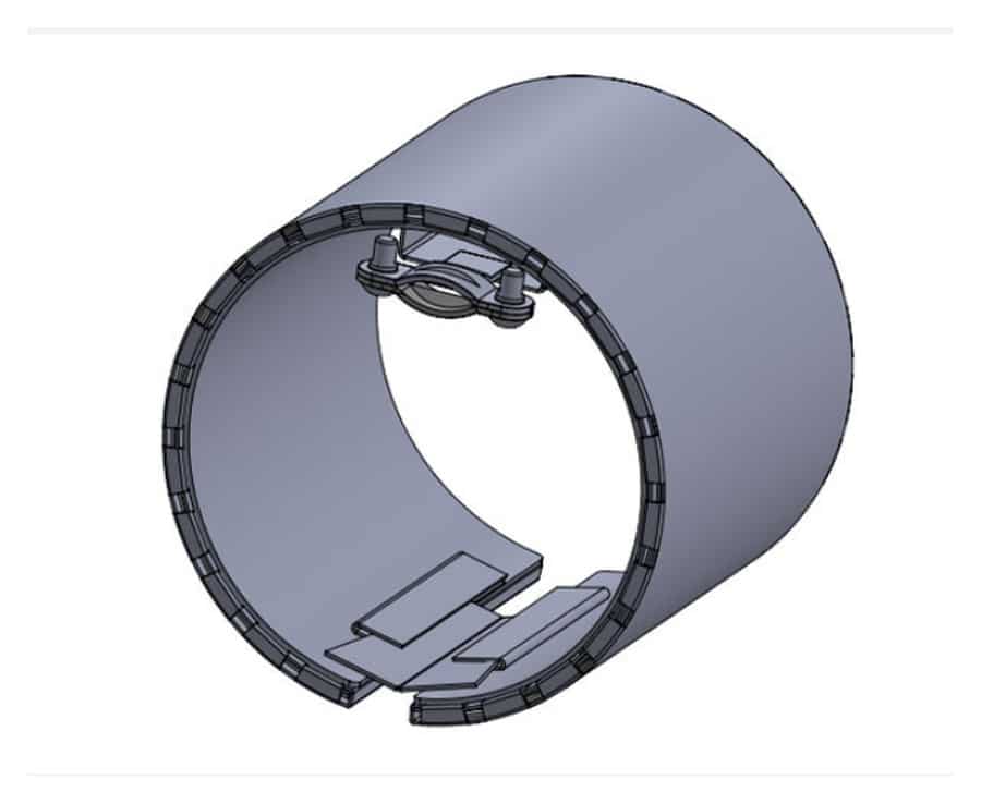
There are three types of fasteners available. Which one is suitable depends on the installation space and mounting position.
Layer Structure
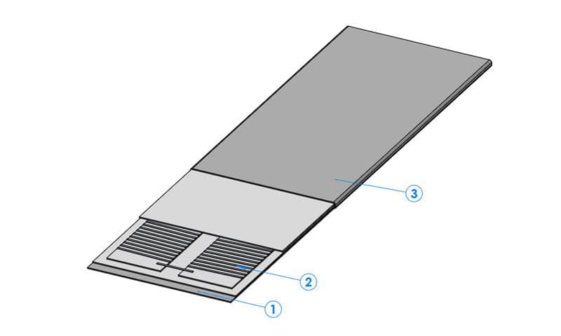
Construction: 1 Cover plate, 2 Insulation sandwich with resistance winding, 3 Inner plate
HKE 54 with additional insulation
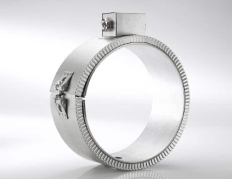
This version features a second layer of insulation directly on the heating tape, as indicated by the ribbed outer jacket. It reduces heat loss to the outside without requiring the installation of a separate insulating jacket.
Design
Layer Structure
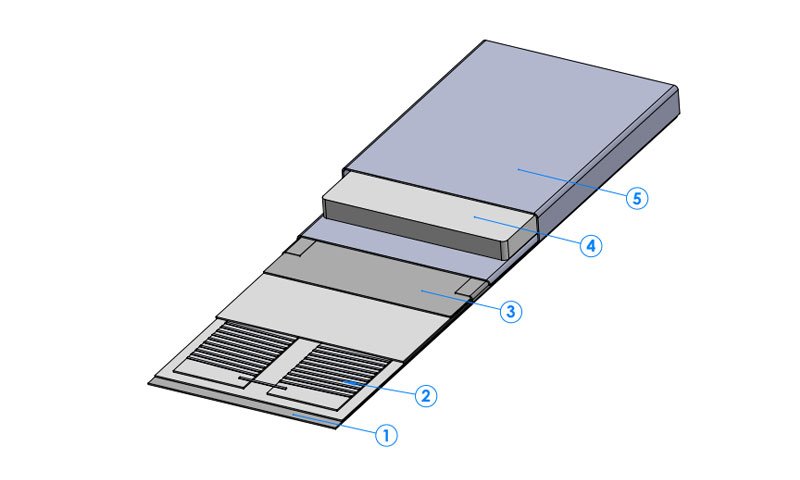
Construction: 1. Base plate, 2. Insulated sandwich panel with resistance winding, 3. Cover plate, 4. Insulation layer, 5. Corrugated outer casing
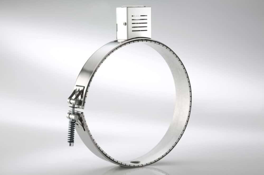
Ring-shaped heating band with a tension clasp
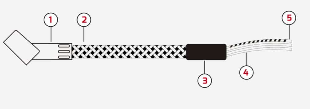
Structure of the connecting cable
| Characteristic | Specification |
| Insulation material | Micanite (mica) |
| Diameter | 30 mm and larger |
| Wide | 20 to 800 mm |
| Max. Surface Load | 4 W/cm² |
| Voltage | 230 V, 400 V, or upon request |
| Operating temperature | up to 350 °C |
| Jacket material | AISI 430 stainless steel |
| Heating conductor Wire | Nickel-Chromium 80/20 |
| Connection Lead | High-temperature-resistant cable with steel braiding, up to 400 °C |
In special cases, these values may be exceeded. The key factor is whether the power can be physically dissipated and the heat removed. Please contact us; we’ll evaluate your application.
For diameters greater than 400 mm, we recommend dividing the pipe into several heating segments.
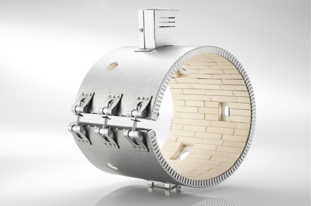
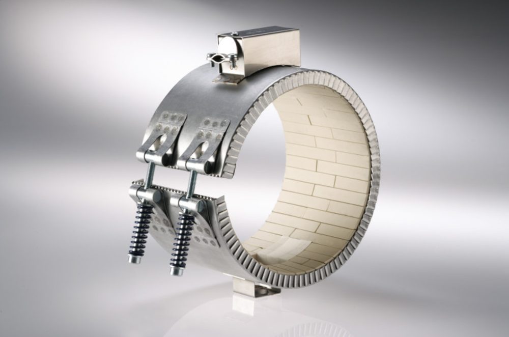
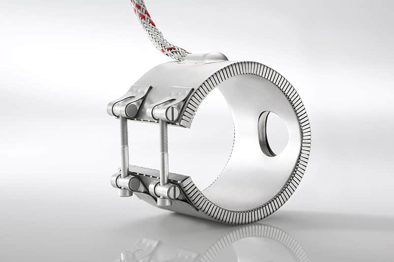
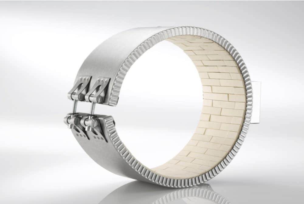
Ceramic heating bands are used wherever cylindrical surfaces need to be reliably heated to high temperatures. The ceramic elements store heat and release it evenly, ensuring that the temperature distribution remains stable even during continuous operation.
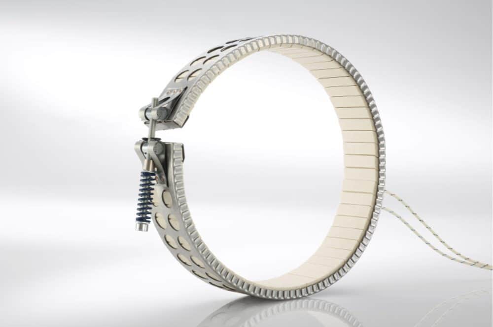
The robust design reduces heat loss and ensures long-lasting, continuous operation. Upon request, we also manufacture ceramic heating bands in a foldable design and as ring-shaped heating bands for round components.
With clamps
With a spring-loaded tension clasp
Single Core connection
| Characteristic | Specification |
| Insulation material | Ceramic fiber |
| Diameter | Ø 60 to Ø 400 mm |
| Wide | 23 to 800 mm |
| Max. Surface Load | 8 W/cm² |
| Voltage | 230 V, 400 V, or upon request |
| Operating temperature | up to 600 °C |
| Jacket material | aluminized steel or stainless steel |
| Heating conductor Wire | Nickel-Chromium 80/20 |
| Connection Lead | High-temperature-resistant cable with steel braiding, up to 400 °C |
In special cases, these values may be exceeded. Please contact us, and we will review your application.
For diameters greater than 400 mm, we recommend dividing the pipe into several heating segments.
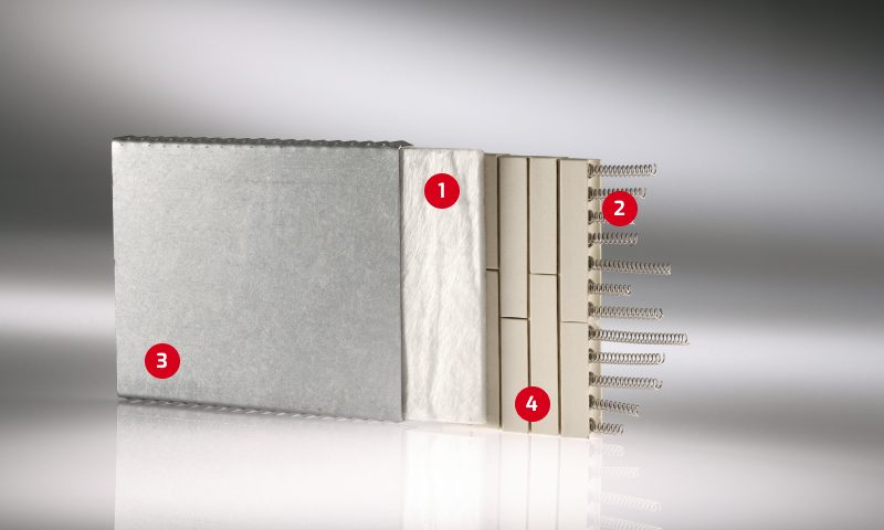
Structure: 1 Ceramic fiber, 2 Heating element, 3 Aluminum-coated steel outer casing, 4 Ceramic elements
Cross-sectional view of the structure
Insulation jackets keep the heat where it's needed. There are two types.
Separate insulating jacket
It is placed over the heating band or over the entire cylinder and fits both mica and ceramic heating bands. It is custom-made, either for a single heating band or for an entire cylinder assembly.
Insulation jacket on the cylinder
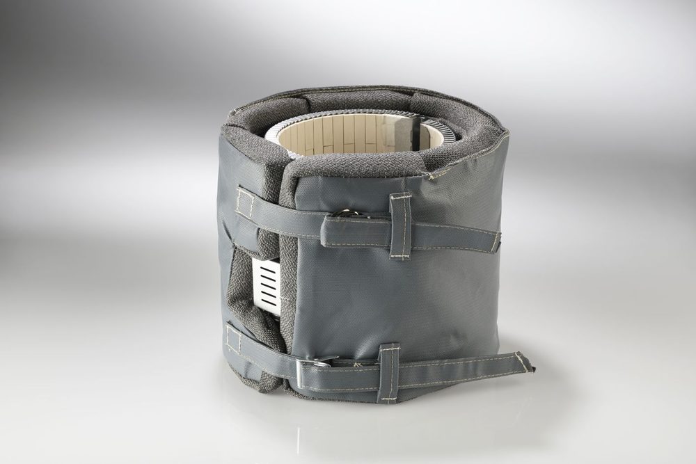
Assembled
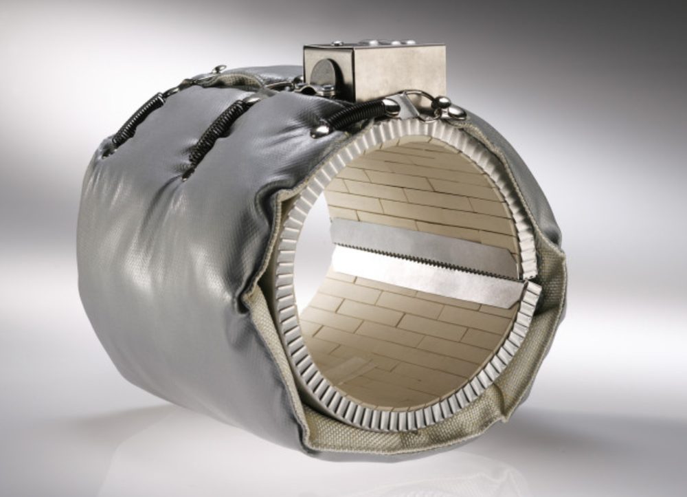
Insulation layer directly on the heating tape
In this version, the insulation is incorporated as an additional layer within the heating cable itself, as indicated by the ribbed outer jacket. No separate jacket is required, and the heating cable has a more compact design. We carry this model as the HKE 54.
HKE 54 with integrated insulation
Layer structure with an insulating layer
The Benefits of Insulation
Energy consumption for heating is reduced by 20 to 40 percent. The surface temperature of the cylinder drops by 60 to 75 percent, which reduces the risk of injury and the heat load in the facility. The heating elements operate at a more constant temperature and therefore last longer.
Calculation example: An injection molding machine with a clamping force of 12,000 kN and ten ceramic heating bands with a combined power of 100 kW saves approximately 1,440 euros in energy costs per year when equipped with insulating sleeves. The investment typically pays for itself in less than a year.
| Characteristic | Specification |
| Inner material | Fiberglass mesh |
| Insulation material | Fiberglass mat |
| Outer material | PTFE-coated glass fabric |
| Operating temperature | up to 500 °C |
| Insulation thickness | 25 mm; other thicknesses available upon request |
| Design | Custom-made for individual heating bands or entire cylinders |
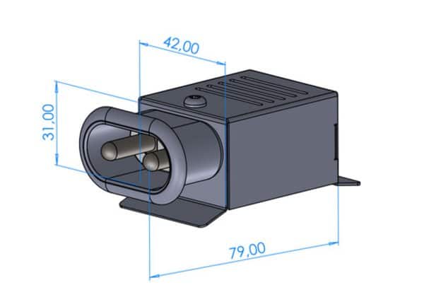
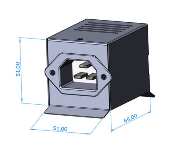
The electrical connection is selected to suit the installation situation. All junction boxes are made of sheet steel and are rated for 230 V and 400 V. The dimensions in the drawings are given in millimeters.
Three designs are available. Axial runs the cable toward the cylinder axis and takes up the least space. Radial It extends vertically away from the cylinder, which is useful when there is limited space on the side. Tangent It runs along the side of the cylinder.
Axial Designs
HKEB-02
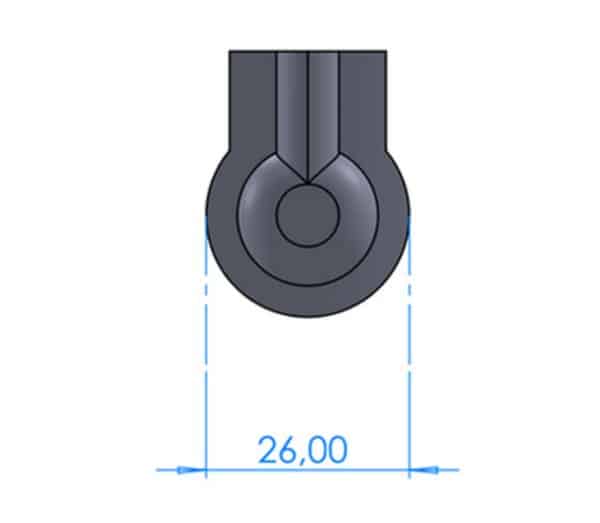
HKEB-05
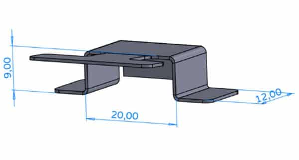
HKEC-10
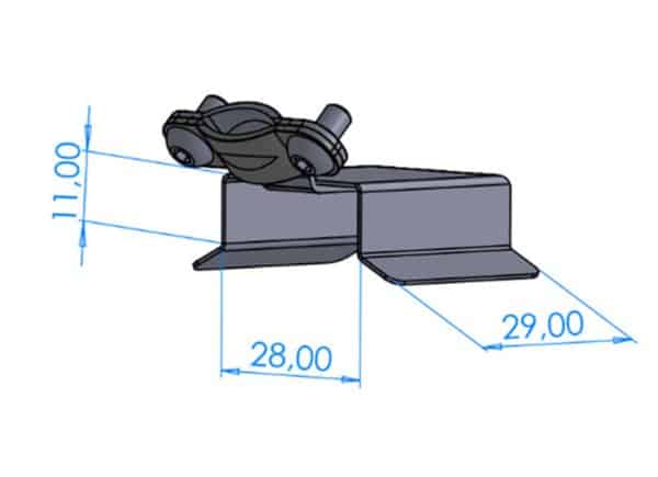
HKEC-20
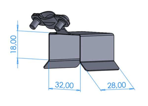
HKECA-10
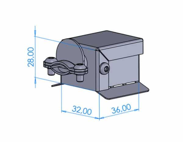
HKECA-20
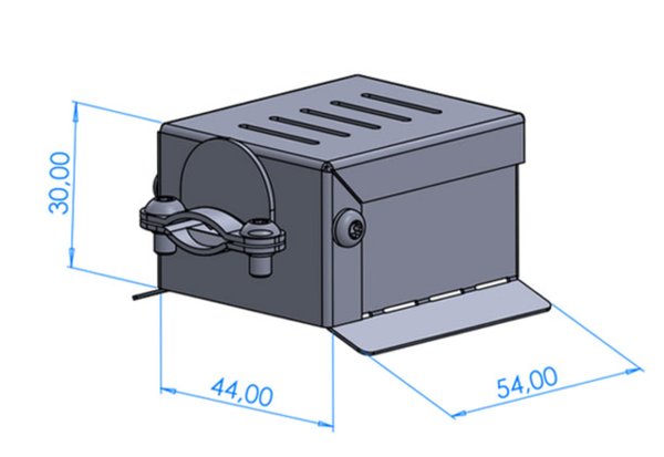
HKECA-25
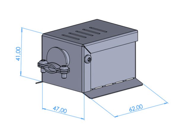
| Description | Load capacity | Cable outlet |
| HKEB-02 | 5 A | EX1, EX3 |
| HKEB-05 | 5 A | EX1, EX3 |
| HKEC-10 | 10 A | EX1, EX3 |
| HKEC-20 | 16 A | EX1, EX3 |
| HKECA-10 | 12 A | EX1, EX3 |
| HKECA-20 | 15 A | EX1, EX3 |
| HKECA-25 | 20 A | EX1, EX3 |
Radial designs
HKECV-10
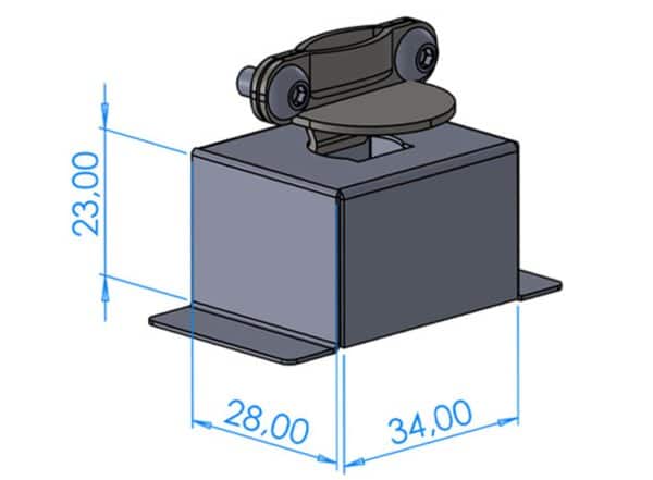
HKECV-15
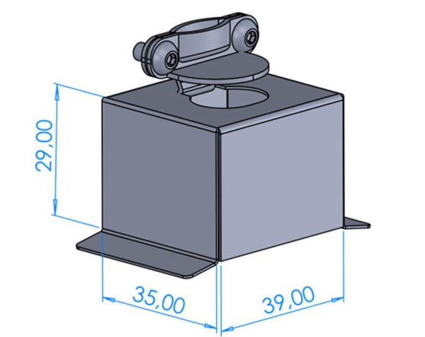
HKECB-15-C
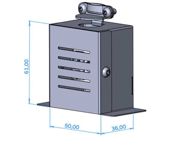
HKECBS-15-3T
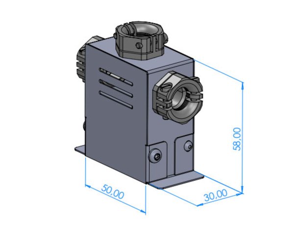
HKECB-80-C
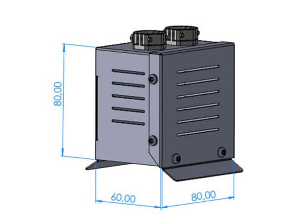
HKESA-5
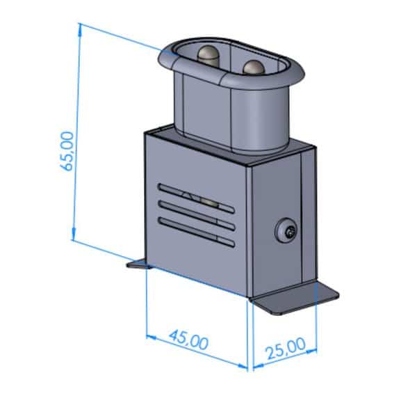
HKESA-EURO
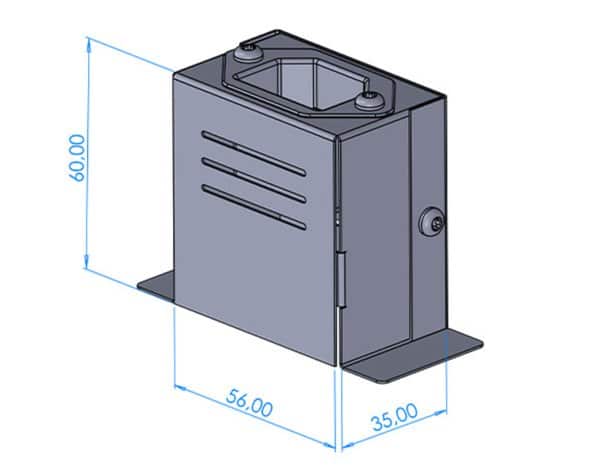
| Description | Load capacity | Cable outlet |
| HKECV-10 | 12 A | EX5 |
| HKECV-15 | 15 A | EX5 |
| HKECB-15-C | 12 A | EX5 |
| HKECBS-15-3T | 12 A | EX2, EX4, EX5 |
| HKECB-80-C | 25 A | EX5 |
| HKECB-90-C | 35 A | EX5 |
| HKESA-5 | 15 A, with built-in outlet | EX5 |
| HKESA-EURO | 16 A, with built-in outlet | EX5 |
Tangential Variations
HKECB-10
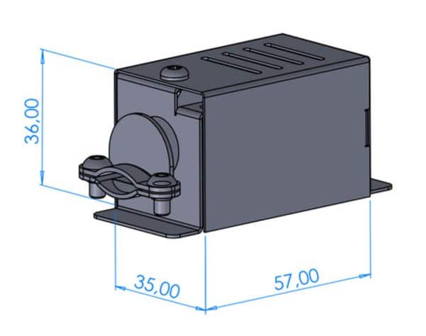
HKECB-15
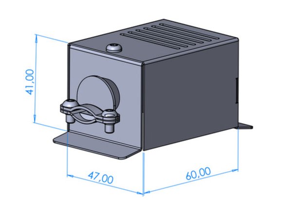
HKECB-20
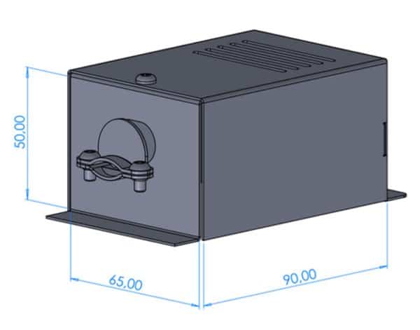
HKECB-30
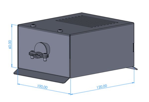
HKECB-40-3F
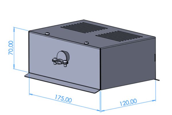
HKECB-15-T
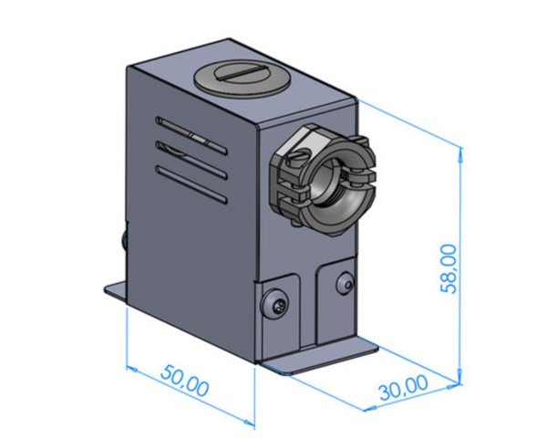
HKECB-15-2T
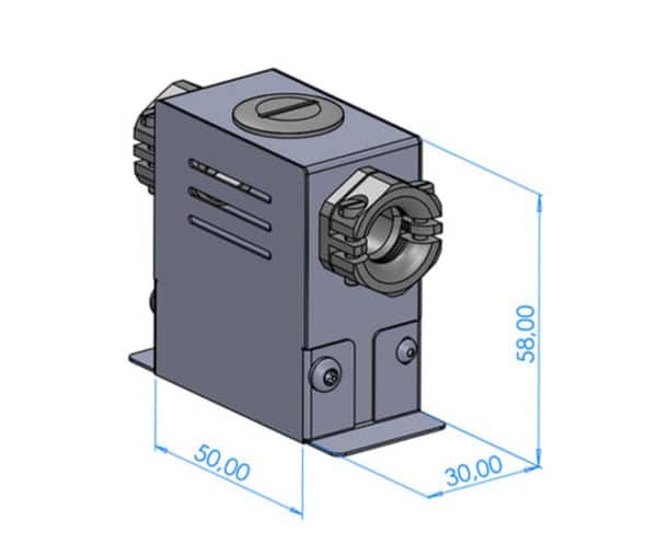
HKECB-15-3T
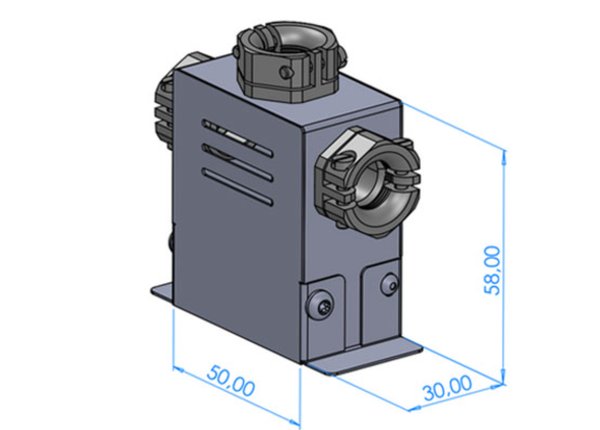
HKESA-5-T
HKESA-EURO-T
| Description | Load capacity | Cable outlet |
| HKECB-10 | 8 A | EX2, EX4 |
| HKECB-15 | 15 A | EX2, EX4 |
| HKECB-20 | 18 A | EX2, EX4 |
| HKECB-30 | 3 x 20 A | EX2, EX4 |
| HKECB-40-3F | 3 x 40 A | EX2, EX4 |
| HKECB-15-T | 12 A | EX2, EX4 |
| HKECB-15-2T | 12 A | EX2, EX4 |
| HKECB-15-3T | 12 A | EX2, EX4, EX5 |
| HKESA-5-T | 15 A, with built-in outlet | EX2, EX4 |
| HKESA-EURO-T | 16 A, with built-in outlet | EX2, EX4 |
Not sure which connector is right for your machine? Send us a photo of the installation, and we'll recommend the right model for you.
Individual designs according to customer requirements
Ceramic heating Band

Ceramic heating Band

Ceramic heater with inner lining

Ring Heating Band

Heating tape up to 300°

Heating tape up to 350°C

Nozzle heating tape long

Nozzle Heating

Heating tape flat 200×120

Heating tape flat 200×200

Heating cooling combination

Heating tape with silicone insulation

Nozzle Heating

Nozzle heater small Ø high power with sensor

Wide version
Single-wire version
Ceramic-Insulated Nozzle Heating Band
Foldable Ceramic Heating Strip
Ceramic heating band