Screw-in heating elements configurator
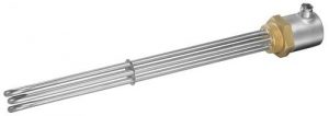
HKE-tec screw-in heating elements made of stainless steel and copper are ideal for heating liquids and gases. They are simply screwed into containers or pipes.
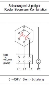
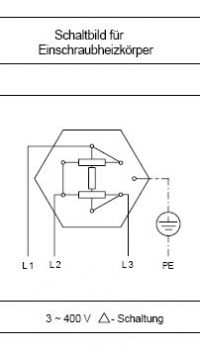
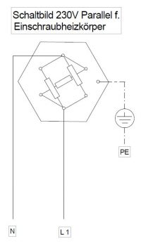
Depending on your needs, they are made of pure stainless steel and can also be welded. There are different switching options such as star or delta. The tube diameter and material are application oriented.
UL certified heaters available upon request.
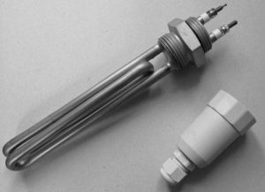
Screw plug tubular radiators from HKE-Tec can be obtained without caps, with plastic caps or metal caps.
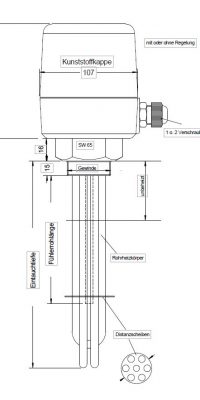
Plastic cap with or without control
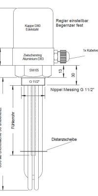
Stainless steel cap with control
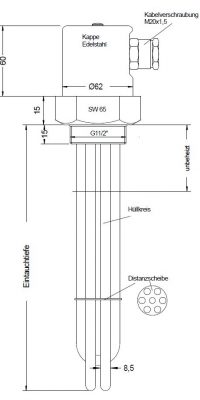
Stainless steel cap or aluminum cap
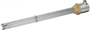
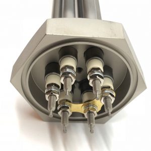
Up to 6 heating elements (depending on the size of the nipple) soldered/welded in a threaded nipple, held together by one or two discs, depending on the immersion depth
Coat Material: Stainless steel or copper
Tube Diameter: 6.5/8.5 or 16.0 mm
Threaded Connection Bolt:
M3 for Ø 6.5
M4 for Ø 8.5
M6 for Ø 16.0
Connection version:
Connection box with temperature controller or limiter
Possible mounting/connection thread:
Thread Nipple m 45 or M 77 as well as 1 ½ ″, 2 ″ or 2 ½ ″
Surface loads:
10 w/cm ² water heating in Continuous heaters
8 w/cm ² water Heating of Moving media
4 w/cm ² water, cleaning bath, heating dormant
2 w/cm ² Light flammable oil, or for gas heating
Print Security:
Up to 15 bar
Voltage:
24V/230 V/400V
Electrical test according to regulations DIN VDE 0700
Performance tolerances: + 10%/-5%
High-voltage strength: 1,250 Volts/1 min
Isolationwiderstand: > 5 MOHM
Comment:
- Care must be taken to ensure that the heated length is covered by the entire medium to be heated.
- In all cases, the thermal expansion of the heating element must be taken into account in terms of room requirements.
Use of the screw-in heating elements
Our screw-in tubular heating elements have different surface loads. Please consider the following limit values when making your selection:
Surface load 2-3 W/cm2: Heating of oil or light grease, e.g. in hydraulic power units
Surface load 4-5 W/cm2: Heating of water or air at a speed of at least 4 m/sec., cleaning and degreasing baths
Surface load 8-9 W/cm2: Heating of fresh water in boilers, running water at a pressure of less than 6 bar
Heat losses
The following empirical values are added to cover the heat losses:
For radiation and convection
20% to 30% for non-insulated containers,
10% to 20% for insulated tanks,
Heat loss for open containers by evaporation
Final water temperature Heat loss per m2 water surface in kWh
40˚C 0,6
60˚C 2,8
80˚C 7,0
95˚C 15,0
The power for the heat of fusion or evaporation shall be added when a substance is melted or evaporates. This power is calculated from the mass (kg) multiplied by the heat of fusion or evaporation in (Wh/kg). In the case of temperature controlled equipment, the heating power may be set at twice the calculated power.
Please note:
Hard water causes lime deposits on the heating elements and can lead to overheating of the heating elements. Calcification can be reduced by reducing the surface load. Water containing free chloride ions also shortens the life of the heating elements.
Product example
